
RT – Step wedge – Results
Results obtained for configurations:
- Flat panel / step wedge made of Dural,
- Flat panel / step wedge made of Ferritic steel,
- Image plate / step wedge made of Dural,
- Image plate/ step wedge made of Ferritic steel,
are shown hereafter.
Flat panel
For each configuration, 5 figures annotated from (a) to (e) are shown. The correspondence of each annotation is given below:
- (a) Profile lines at the “full beam” / “full wedge” transition (green lines in figure below),
- (b) Profile lines along the steps (red lines in figure below),
- (c) Profile lines along the holes (blue lines in figure below),
- (d) Profile lines along the first Image Quality Indicator (IQI, NF EN ISO 19232-1 W10) (purple lines in figure below),
- (e) Profile lines along the second IQI (NF EN ISO 19232-1 W13) (purple lines in figure below).
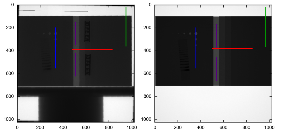
Positions of the profile lines for the flat panel on the experimental image (left) and the simulated image (right).
The time of exposure has been adapted so that the experimental and simulated gray levels are similar on particular regions of interest. The region of interest has been chosen in the “full wedge” area that is to say on a part of the detector which receives the radiation which has crossed the largest possible wedge thickness. If this retiming makes it possible to better compare experimental results and simulation results by matching the gray levels obtained outside the reliefs (holes and steps), it generally involves a difference between simulation and experience on the gray levels recorded in “full beam”.
Retiming is carried out via the “post-processing” tool, available in CIVA.
Dural wedge
Results are illustrated below.
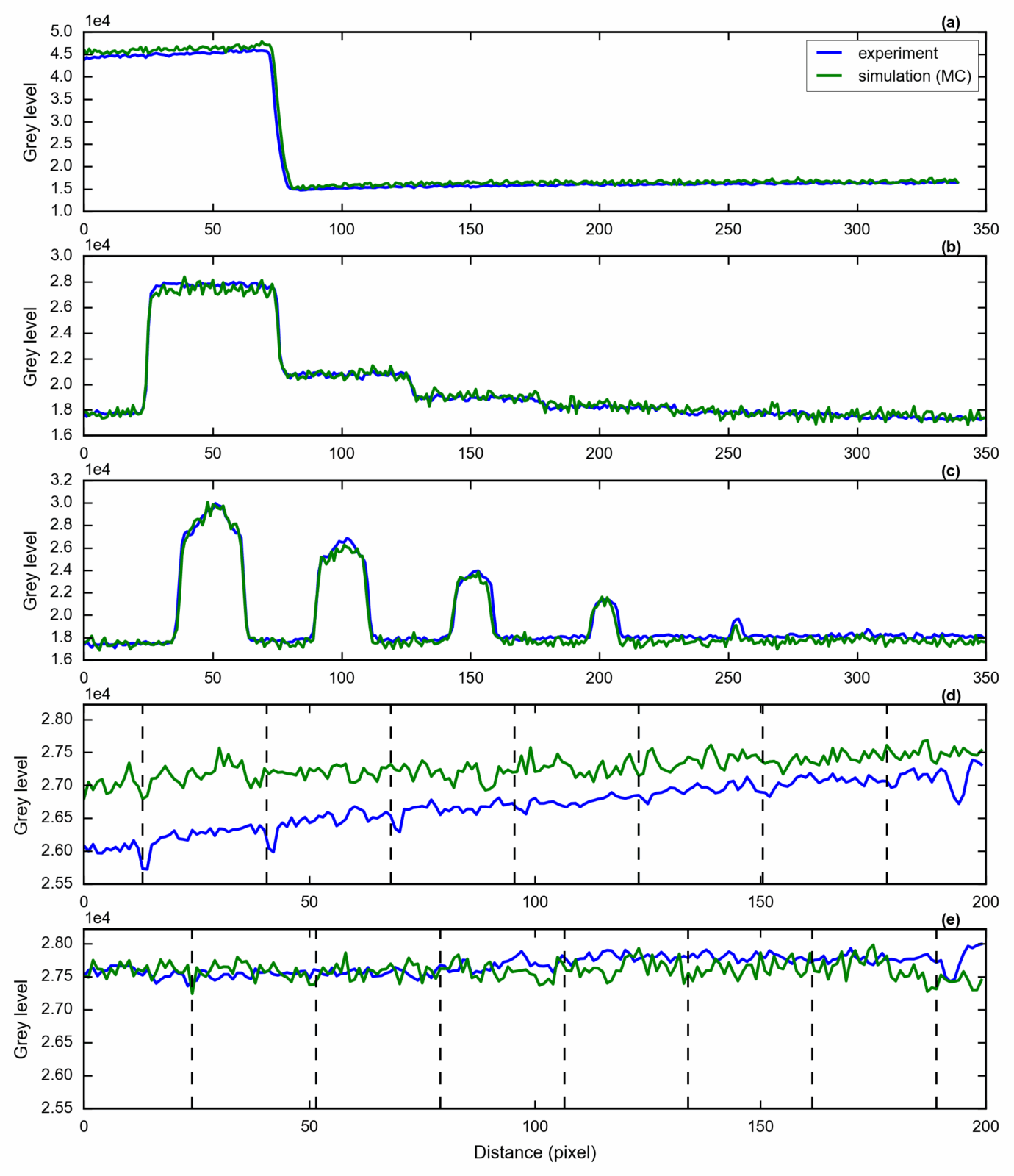
Comparison between simulation and experiment for the Dural plate (flat panel), with the digital radiography detector model.
Nb: “MC” refers to the case where the calculation was made using the combination of direct and scattered radiation.
Nb: The profile lines along the IQI are measured where they are most apparent (when they are) in the experimental image. The approximate positions of the IQI wires are indicated by vertical dotted lines on graphs (d) and (e).
The noise levels observed are illustrated in the table below.
| Experiment | Simulation (MC) | |
| Noise level | 119 | 288 |
ferritic steel wedge
Results are illustrated below.
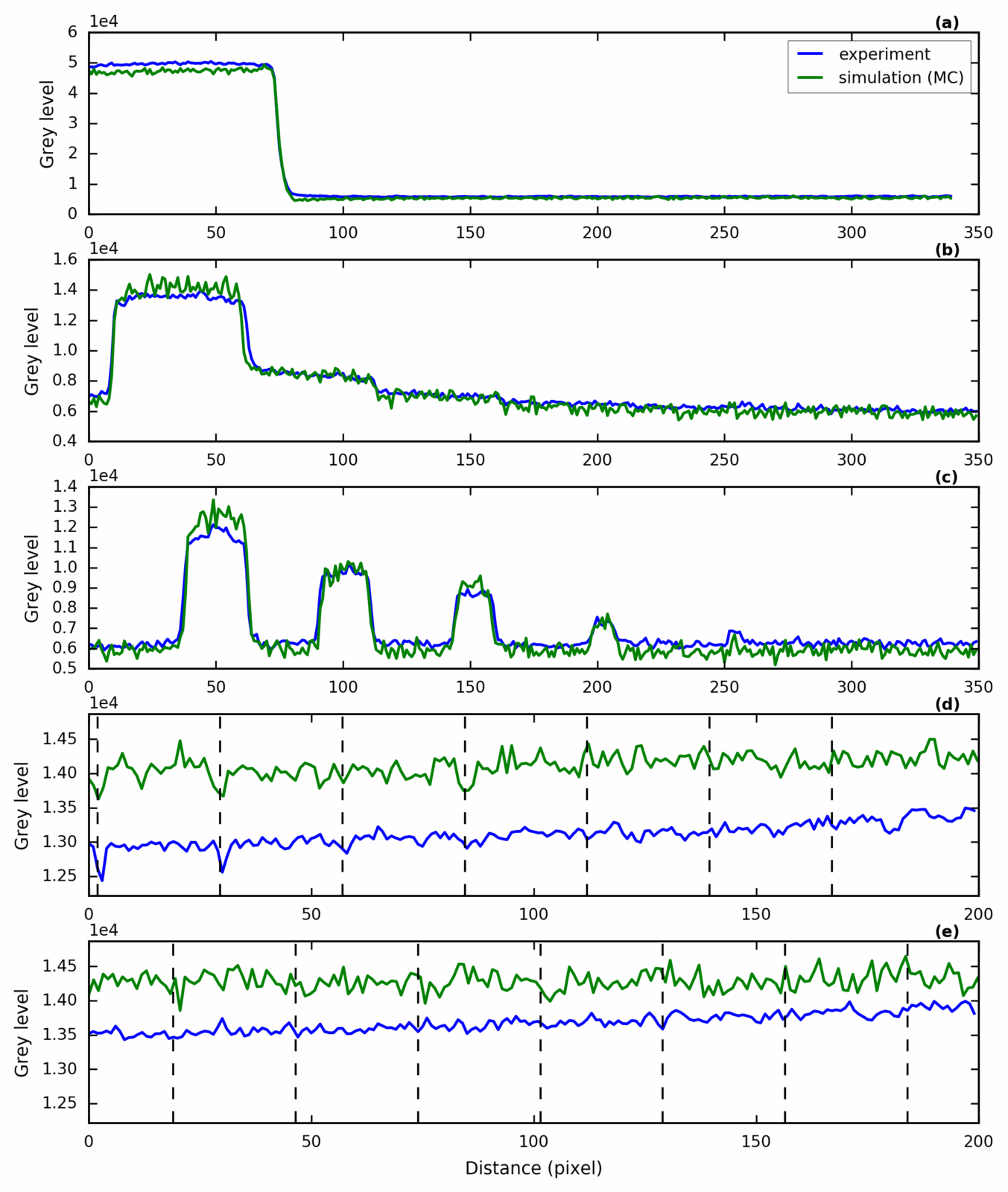
Comparison between simulation and experiment for the ferritic steel plate (flat panel), with the digital radiography detector model.
Nb: “MC” refers to the case where the calculation was made using the combination of direct and scattered radiation.
Nb: The profile lines along the IQI are measured where they are most apparent (when they are) in the experimental image. The approximate positions of the IQI wires are indicated by vertical dotted lines on graphs (d) and (e).
The noise levels observed are illustrated in the table below.
| Experiment | Simulation (MC) | |
| Noise level | 97 | 247 |
Image plate
For each configuration, 4 figures annotated from (a) to (d) are shown. The correspondence of each annotation is given below:
- (a) Profile lines along the steps (red lines in figure below),
- (b) Profile lines along the holes (blue lines in figure below),
- (c) Profile lines along the first Image Quality Indicator (IQI, NF EN ISO 19232-1 W10) (purple lines for the Dural plate and green lines for the ferritic steel one in figure below),
- (d) Profile lines along the second IQI (NF EN ISO 19232-1 W13) (purple lines for the Dural plate and green lines for the ferritic steel one in figure below).
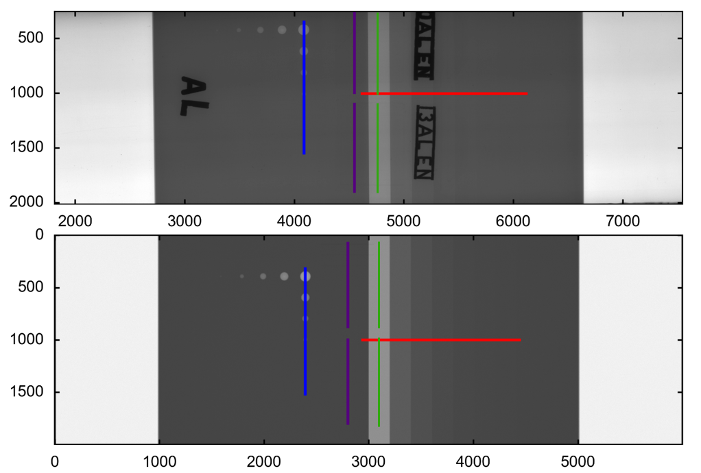
Positions of the profile lines for the image plate detector on the experimental image (left) and the simulated image (right).
As for comparisons made for flat panel, a post-processing is realized on the simulated images.
Dural wedge
Results are illustrated below.
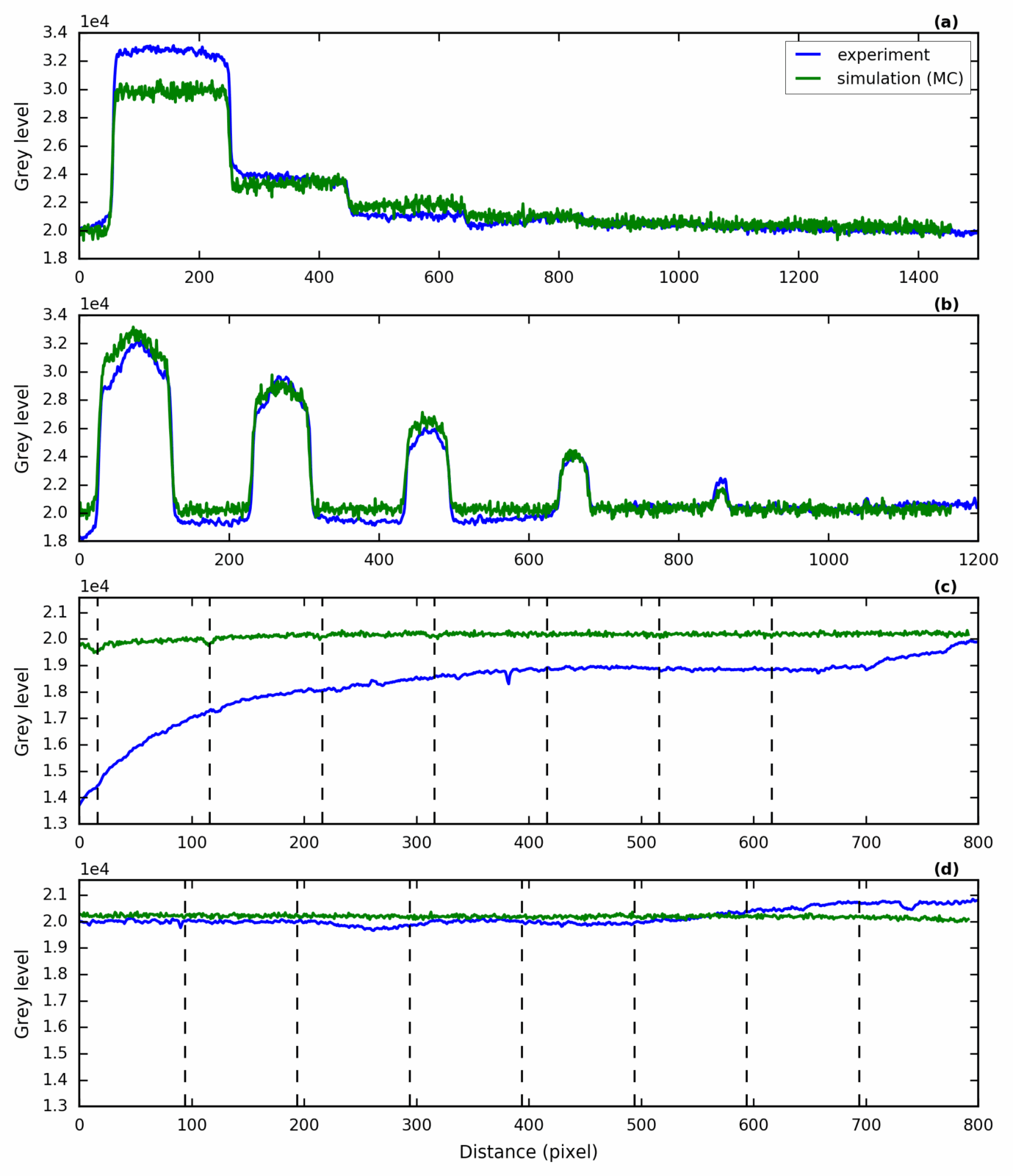
Comparison between simulation and experiment for the Dural plate (image plate), with the computed radiography detector model.
Nb: “MC” refers to the case where the calculation was made using the combination of direct and scattered radiation.
Nb: The profile lines along the IQI are measured where they are most apparent (when they are) in the experimental image. The approximate positions of the IQI wires are indicated by vertical dotted lines on graphs (c) and (d).
The noise levels observed are illustrated in the table below.
| Experiment | Simulation (MC) | |
| Noise level | 142 | 264 |
Ferritic steel wedge
Results are illustrated below.
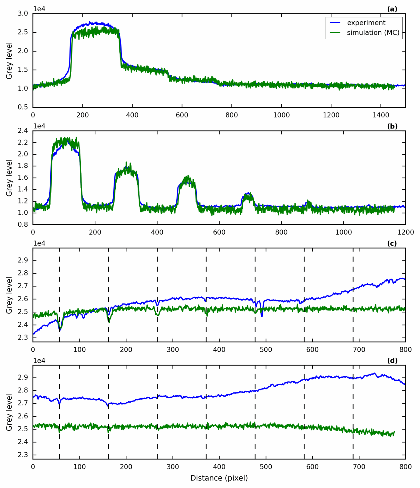
Comparison between simulation and experiment for the ferritic steel plate (image plate), with the computed radiography detector model.
Nb: “MC” refers to the case where the calculation was made using the combination of direct and scattered radiation.
Nb: The profile lines along the IQI are measured where they are most apparent (when they are) in the experimental image. The approximate positions of the IQI wires are indicated by vertical dotted lines on graphs (c) and (d).
The noise levels observed are illustrated in the table below.
| Experiment | Simulation (MC) | |
| Noise level | 91 | 382 |
Continue to Analysis
Back to Modeling using CIVA
Back to Step wedge made of Ferritic steel and Dural